| Displacement mapping | |
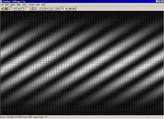 |
I've created some displacement maps that can be used for this tutorial and you can download from here (156K). Start UVMapper Pro and select File->New Model->Sphere. Because the displacement map we're using for this is square, change vertical divisions to 64 (same as horizontal) and press OK. When using displacement mapping it's usually a good idea to triangulate the model first to avoid artifacts from non planar facets, so press 't' to triangulate the model. Select Texture->Load to load combo.bmp (from the zip file above) into the background. I created this map by rotating a sin wave 45 degrees (diagwave.bmp) and multiplying it in Photoshop by a vertical sin wave (vsinwave.bmp). Both are included in the zip. |
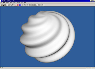 |
Press tab for the 3D view and select Tools->Vertices->Displace. Use the default values except change the max offset to 0.4 units. Vertices on the black portion of the map will be displaced by the min offset while those on the white portion will use the max offset. After using the displace vertices tool, we need to smooth the model because the facets have all moved. Do this by selecting Tools->Normals->Smooth and use a smoothing angle of 180 degrees. Select View->Texture so we no longer see the displacement map on the model and your screen should look something like this. Simply export the model and load it into your favorite rendering program. It's just that easy. |
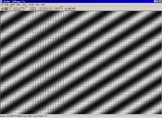 |
Now select File->New Model->Torus, change the vertical divisions to 64 and press OK. Select Tools->Facets->Triangulate and press YES (does the same thing as pressing 't'.) Press control+b and load diagwave.bmp into the background. Note that the displacement map runs in the same direction as the diagonals of the model facets. This will give the best results with displacement mapping. If you're using a model where these are reversed, you can flip the displacement map horizontally or vertically in UVMapper by pressing shift+control+u or shift+control+v (these are also on the Texture menu.) |
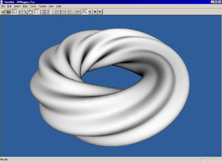 |
Press tab for the 3D view and select Tools->Vertices->Displace. Use the default values and a max offset to 0.4 units. Smooth the model by selecting Tools->Normals->Smooth and use a smoothing angle of 180 degrees. If the texture map is displayed, select View->Texture from the menu to turn it off. Export the model and render it in your rendering program. |
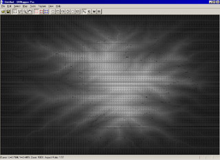 |
You can also create terrains from height fields using displacement mapping. Select File->New Model->Plane from the main menu. Use 128 for width, height and both divisions (if you have a fast computer, you can bump this to 256 for better results.) press 't' to triangulate the plane. Press control+b to load terrain.bmp into the background. |
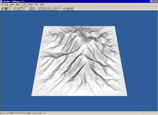 |
Press tab for the 3D view. Select Tools->Vertices->Displace from the main menu and use 32 as the max offset (64 if you're using a 256 x 256 plane.) Select Tools->Normals->Smooth and smooth using an angle of 180 degrees. Export to your rendering program. (I think you're starting to get the hang of this.) |
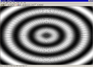 |
This time, we're going to use a cylinder. Use the defaults except use 1 for height divisions, 64 for top divisions and 0 for bottom divisions (this may take a while to create - here on my PII-300 it takes about 45 seconds.) Use the rectangular marquee to select the sides and bottom of the cylinder and press delete to remove these facets. Now select all (control+a) and press '=' to maximize the selection. Press enter to save the changes. Load radial.bmp as the background. Since the displacement is along the radial lines, I don't think we'll need to triangulate the model this time. |
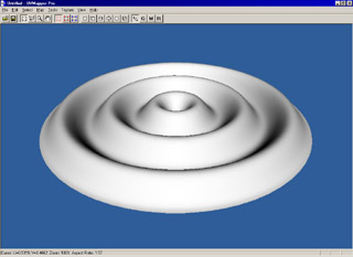 |
Press tab for the 3D view. Select Tools->Vertices->Displace and use an offset of 0.2 this time. Select Tools->Normals->Smooth and smooth using an angle of 180 degrees. Be sure View->Texture is unchecked and your screen should look something like this. |
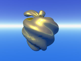 |
This method will work with any model that has texture coordinates not just UVMapper Primitives. Here I've used a model of an apple and displaced the vertices using diagwave.bmp. I don't know how well this technique will work for morph targets since it tends to cause facets with four or more vertices to become non planar. All the vertices may no longer be in the same plane - a big no-no for most rendering programs. I'd love to hear about your successes (or failures) with displacement mapping. You can get in touch with me using the "contact me" link below. Now go and see what you can come up with... |