| Creating sharp edges with auto-smooth | |
|
|
The first thing you'll need for this tutorial is my model of a die, which you can get here (22k). Once you have download the model and unzipped it, start
UVMapper Pro and load it. This model has no materials, texture coordinates or normal vectors. We'll be adding
all of these in the following steps.
It's a good idea when you start working with a new model to check for and repair concave, degenerate and collinear facets. You can do this by using the Tools->Facets menu items. Unless I've made a mistake, you won't find any of these in my model. |
|
|
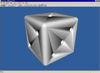
We'll start by welding the vertices (Tools->Vertices->Weld) to be sure we're starting with a clean slate. Next we'll smooth the model (Tools->Normals->Smooth) so that we can see what it will look like when imported into a program such as Poser. The default setting is "Using all facets" which we want, but to simulate auto smoothing we'll use a smoothing angle of 180 degrees. After doing this, your screen should look like the image on the left. This is pretty much how the model will look if we were to import it into Poser at this point. To see a before and after example rendered in Poser, click here Compare this to the image on the left, and the one below it. |
|
|
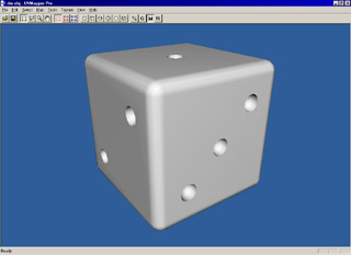
Now we'll split the vertices that surround the holes in the die. Do this by selecting Tools->Vertices->Split. We want to split using all facets, a splitting angle of 43 degrees and auto smooth the model. Since these are the default settings, just click on OK. By adjusting the splitting angle you can change the threshold at which hard edges will appear. In this case, any facets that are facing more than 43 degrees away from each other will now have a hard edge between them when auto smoothed. Auto smoothing the model simply does the same thing as Tools->Normals->Smooth using all facets and an angle of 180 degrees. Your screen should look like this. |
|
|
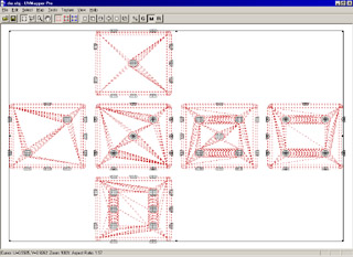
Press tab to switch to the 2D display. Select Map->Box and accept the default values by pressing OK. Right click on one of the facets that make up the white portion of the die and choose "Select Geometry" from the popup menu. Your screen should now look like this. Note that none of the facets that make up the dots are selected because we split them off in the last step. Since they no longer share vertices with the rest of the model they aren't part of the same geometry. This makes it very easy to split up the model for assigning materials. Choose Tools->Assign to->Material from the main menu, type in "white" and click OK and then YES. |
|
|
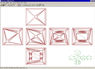
Pressing control+shift+I will invert your selection. Select Tools->Assign to->Material again from the main menu, type in "black" this time and click OK and then YES. Press the keypad "/" twice to make the selection smaller and move it to the lower right corner. This way we can map the dots independently later if we want. Your screen should look like this. |
|
|
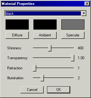
Press tab to return to the 3D view. Select Tools->Materials from the main menu. Select the material "black" and click on the diffuse button to change the color to black. Click on the specular button and choose a medium gray. Finally, change the shininess to around 400 and click OK. That's about it for UVMapper Pro. Save your work using the default settings, and exit. |
|
|
Start your 3D program that uses auto smoothing. For demonstration purposes I'm
using Poser 4. Load the model and render. Your results should look something like this. Note: for some
reason, Poser seems to ignore the shininess entry in the material library. I had to go to Render->Materials, select
the black material and set the highlight size to 100% in order to get highlights to appear in the black dots. You
shouldn't have this problem with other 3D programs.
And there you have it - a model in Poser with both smooth and sharp edges without requiring any additional facets. |

